Wearable Technology and eTextiles
Kitronik 'Live brief' for SKE students
Context
Kitronik supply schools and hobbyists with a range of products that are focused on 'Design and Technology'. They have specialist skills in the electronics aspects of design and technology, and have developed a number of their own products. Formed in 2005, the team have over 10 years of electronics design experience. They believe that all students should be able to access and experience electronics and are keen to promote this exciting and ever relevant area of the curriculum.E-textiles are a growing area of their product portfolio and they believe, along with Leah Buechley (2006) that this field of study has the potential to appeal to a “different class of user” within electronics. This assignment is a live brief, designed by Kitronic along with tutors at NTU to challenge SKE students to work with integrated materials and technologies through the use of electronics in a textiles context.
Design Brief
In groups of 3 create a range of teaching resources that include: (1) a video tutorial for an aspect of your resource, (2) a high quality photograph of a wearable eTextile product, on the theme of 'well-being', 'personal expression' or 'being seen' and (3) an instructable type webpage tutorial, to describe your design process for the wearable eTextile product.
As part of this project you will need to:
- Become familiar with how to teach the manufacture of one of the soft components in order to make the video;
- Manufacture an eTextile product that meets the brief;
- Consider how to stage your photograph to best show off your product;
- Become familiar with the instructables website; and
- Consider how you will describe your design and make process for an education audience.
To help you with this you will have the opportunity to:
- Take part in the Tinkering workshop during the project launch with Sarah Davies
- Select free electronic resources from the Kitronik Electro-Fashion range
- Access specialist tools and equipment in MAU118 (throughout the D&M sessions)
- Feedback on ideas from Kevin Spurr (TBC)
- Reference to previous instructables/Kitronik webpages created by Sarah and students from the ITE courses at NTU
We had a go making circuits using “tinkering kits” which included a piece of conductive fabric. The tinkering kit extension pack included more LEDs and crocodile clips so that we could learn how to make a parallel circuit.

Circuits tinkering.jpg

Sewn circuit 1.jpg

Sewn circuit off.jpg

Sewn circuit on.jpg
Day 2 - 22 June 2017(Self-led day)
Making a soft battery holder (powerboard)
- Sew contact onto one piece of felt with conductive thread, through conductive fabric on the other side.
- Sandwich together with positive piece of conductive fabric on inside (negative bit on outside).
- Sew around pocket shape for battery.
- Layer felt, conductive fabric, net, felt with hole, conductive fabric, felt.
- Sew around. When pressed, the conductive fabrics make contact through the small holes in the net.
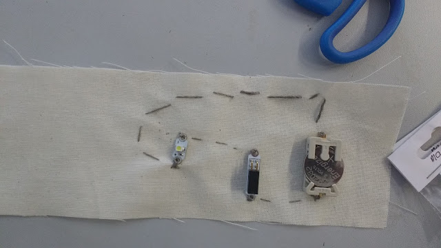
Darryl and I made a successful battery holder and soft switch:

Soft switch and battery holder.jpg
(Competencies: T.M.3.9, T.M.3.13, T.K.3.4, T.K.3.6)
We started to consider the “being seen” brief and made a few mind maps and ideas sheets. These document our conversations and ideas in quite a messy way. I find writing is faster to get a thought or idea down, then sketches help to explain or figure out a particular thought.
(We weren't sure whether all three brief themes were still active, but the class seemed to agree that “being seen” had been specified/chosen so we stuck with that in the end.)

Design
and make 1.jpg

Design
and make 2.jpg

Design
and make 3.jpg

Design
and make 4.jpg

Design
and make 5.jpg
Darryl's
pages look a bit tidier than mine!

Design
and make Darryl 1.jpg

Design
and make Darryl 2.jpg

Design
and make Darryl 3.jpg
It felt like we should have found some better ways to think up designs and be creative. We felt a bit limited by the “being seen” brief and then by not knowing how complex our technology could be. I guess the main preoccupation was thinking up/choosing a “problem” to solve.
(Competencies: C.1, C.4, C.5, C.6)
Can
we hack a neon strip to run on cell batteries? (AAA batteries are
too bulky for a wristband.)
Size?
Fit? Elastic?
Should
we use programming?
What
can of switches could/should we incorporate?
Lighting
effect / layout of LEDs?
Darryl
quickly discovered from calculations and then testing that the neon
strip would not work on cell batteries.
He
then found out from the Kitronic website that it should be possible
to run 6 LEDs from one cell battery for 2 hours. He set up 12 LEDs
in parallel with crocodile clips to one battery to see whether it
worked (and just for fun).


I found a scrap of denim and made a few testers:
1. Just elastic – turns out to be too loose with just a small section of elastic but it would be very difficult to incorporate our electronic components into a fully elasticated band.


Then Darryl mocked up a quick test on fabric.


Parallel circuit 1.jpg

Parallel circuit 1.jpg
1. Just elastic – turns out to be too loose with just a small section of elastic but it would be very difficult to incorporate our electronic components into a fully elasticated band.

Elastic no fastening.jpg
2. Elastic and velcro – fits better but feels a bit “home made” on the fastening front.

Elastic and velcro.jpg
3. Poppers – can adjust the fit and they look quite nice in a pattern. I would prefer to used rivet-style press studs for a cleaner, more professional look.

Adjustable poppers.jpg
We ruled out using a programmable part (Kitronic Igloo) pretty quickly because of the size of the board in relation to our wristband. But we had a go at using the PICAXE Blockly software and found it was fairly usable, except for hardware issues with the specialised wire.
We talked about having a tilt switch, so that when you lift your arm to wave the LEDs come on, but weren't keen on the idea of a bead (or other conductive contact) swinging around, like
the example we had been shown. We could have tried a weighted
element moving around inside somehow, but it seemed clear to us that
this would be too squashed inside a wristband to move freely. We
even discussed ball bearing mazes (like in cheap children's toys and
Christmas crackers) so that the switch would be an enclosed unit.
Eventually,
we were given a Kitronic ball bearing tilt switch, which does exactly
the job we need. We tested it by taping it to Darryl's arm.

Tilt
switch test 1.jpg

Tilt
switch test 1.jpg
Then Darryl mocked up a quick test on fabric.

Tilt
switch test 3.jpg
Darryl
has been drawing up some circuits using one or two batteries based on
parallel lines.

Circuit
ideas.jpg
I
made a pattern of square LEDs that could be covered with a stencil to
make an initial/image. This was deemed too low tech (naff). W could
have explored how this effect could be programmed to display images
or initials, but we didn't go down this route. It was noted,
however, that a square of 16 LEDs would have a really strong impact.

Square
1.jpg

Square
2.jpg
Towards
the end of the day, I nipped out to the Victoria Market to find some
rivet press studs, because we quite liked having the pattern of
poppers running along the band. There were a couple of choices (and
sizes, but I got the smallest I could find of each for our little
wristband) and I picked up some magnetic fasteners too, in case they
looked interesting.

Press
studs.jpg
A
reflection:
I
got frustrated by being presented with all the available electrical
components at the end of the day. I can understand that having
everything ready-made would limit our creativity and perhaps stop us
thinking as broadly as we had to to solve problems without
components. However, being able to discover the possibilities at an
earlier point would have stopped our feeling of being restricted by
not knowing.
Day 4 - 27 June 2017
After yesterday feeling a bit frustrating, we started off with a bit more vigour today. We decided quickly on a circle of LEDs for our design, based on the circle of the 10mm press-through poppers I'd found. (This is a picture of the rivet-style press studs laid out on top of our original sewn-on ones.)

Darryl suggested we try a velcro fastener that looped back over itself to be more adjustable. This works well because it feels “right” and gets a better fit. We bit the bullet and decided on that over the popper design.
We weren't left with much space for the LEDs, so we tried out having a longer overlap. This gives us more space to work in and more space to hide batteries, etc. It will make it a thicker, more substantial wristband but we're hoping it won't be bulky.


We found a small piece of a neoprene kind of fabric. I immediately felt it would melt really nicely with a soldering iron, which would be ideal for making the small holes for the LEDs, so we did a test (and it worked).

So we went shopping but couldn't find any neoprene. Instead, we chose heavy duchess satin that feels synthetic enough that it will melt and has a similarly pleasing solidness to it as the neoprene. We did another quick melt test.

We started to lay out the pattern for the fabric. Will need to reinforce the satin with some kind of interfacing, especially the band that the strap pulls through and the section that needs to support all the electronics.
A the same time we were working on a double battery holder, connecting the batteries next to one another.


It didn't work. You don't run batteries in series, they have to sun in parallel. Darryl knocked a couple of separate holders to make sure...

...then our second double battery holder (with 4 separate connectors, 2 pos, 2 neg) worked fine – and we took the opportunity of remaking to change where the contacts would exit the holder.

Darryl has been sketching out circuits to run LEDs in parallel in a circle. We're sticking with the circle design even though it doesn't link in with the press stud fastener any more – it will still have good visual impact. Made a few tester circuits.


Rivet poppers.jpg
Darryl suggested we try a velcro fastener that looped back over itself to be more adjustable. This works well because it feels “right” and gets a better fit. We bit the bullet and decided on that over the popper design.
We weren't left with much space for the LEDs, so we tried out having a longer overlap. This gives us more space to work in and more space to hide batteries, etc. It will make it a thicker, more substantial wristband but we're hoping it won't be bulky.

Velcro trials.jpg

Velcro layout 1.jpg

Velcro layout 2.jpg

Velcro layout 3.jpg

Velcro layout 4.jpg
We found a small piece of a neoprene kind of fabric. I immediately felt it would melt really nicely with a soldering iron, which would be ideal for making the small holes for the LEDs, so we did a test (and it worked).

Neoprene melt test.jpg
So we went shopping but couldn't find any neoprene. Instead, we chose heavy duchess satin that feels synthetic enough that it will melt and has a similarly pleasing solidness to it as the neoprene. We did another quick melt test.

Satin melt test.jpg
We started to lay out the pattern for the fabric. Will need to reinforce the satin with some kind of interfacing, especially the band that the strap pulls through and the section that needs to support all the electronics.
A the same time we were working on a double battery holder, connecting the batteries next to one another.

Original double battery holder 1.jpg

Original double battery holder 2.jpg
It didn't work. You don't run batteries in series, they have to sun in parallel. Darryl knocked a couple of separate holders to make sure...

Separate battery holders.jpg
...then our second double battery holder (with 4 separate connectors, 2 pos, 2 neg) worked fine – and we took the opportunity of remaking to change where the contacts would exit the holder.

Working battery holder.jpg
Darryl has been sketching out circuits to run LEDs in parallel in a circle. We're sticking with the circle design even though it doesn't link in with the press stud fastener any more – it will still have good visual impact. Made a few tester circuits.

Test circuit 1.jpg

Test circuit 2.jpg
Day 5 - 28 June 2017
Darryl had laid out the circuit to include 8 LEDs in the circle but I felt quite strongly that it would have a significantly better impact with 10 (or even 12). Also, we are going to the trouble of using 2 batteries, so I felt we should make more use of them. Darryl's main worry was that they would be closer together so the likelihood of them touching and short circuiting would be increased. I was confident that they would fit and demonstrated to him how his “tram lines” could be more strategically placed – so that the LEDs would come directly into contact with them.

Final circuit marked out.jpg
Machine sewing can be extremely accurate, and as this was something holding Darryl back, I sewed the lines once he had marked them out.

Final tram lines.jpg
I then hand-stitched the LEDs on, making sure to have a good contact with the trams lines each time, which are now on the reverse side of the fabric.

Tram lines and LED.jpg

LED circle.jpg
So now it all works, Darryl individually lined up and melted each hole in the black satin. (As this piece of satin doesn't have anything affixed to it, it felt like we could just go for it and if the melting didn't go very well, we could just cut another piece. But we didn't need to because Darryl's first effort was good enough.) We had a few thoughts on how to keep the LEDs showing through the holes (sewing a circle around, hot glue gun the centre and outside etc.) but eventually went for the low-fi UHU glue option around each LED and it worked really well. (This photo also shows our test that found melting a hole in interfacing doesn't work, so we cut a whole circle section away from the LED area.)

UHU glue.jpg

LED circle satin.jpg
As you can see, whilst all the electrical working out had been going on, some fabric things were happening too. We used out pink sketch model to draw out a paper pattern, adding seam allowance. We cut out the fabric and interfacing together – we need only one of each pattern piece.

Fabric layout.jpg
Then we basted the interfacing onto the reverse of each piece, stitching inside the seam allowance, not on the stitch line.
We had decided to incorporate the battery holder as a pocket, and to do this it had to be stitched very precisely onto each wristband section, then the seam completed either side to leave the pocket open in the centre.

Attaching battery holder.jpg

Battery holder in seam.jpg
The velcro and the strap restraint could then be added.

Band with velcro.jpg
We were now ready to “bag out” the wristband – sewing it together inside out, leaving a small section open, and then turning it the right way so that the fabric edges are enclosed inside.

Bagging out 1.jpg

Bagging out 2.jpg
Once sewn, when turning inside out, the corners need to be trimmed (or clipped) so that there isn't a bulky excess of fabric on the inside.

Clipping corners.jpg
Once it was turned out it was very apparent that the wristband was way too bulky and because of the bulk, it was also far too short. The restraint band also did not lie flat because I had not taken the bulk into account and had stitched it flat into the seam.
We removed some interfacing and took the decision to add a section to the non-LED end of the wristband, to increase the length. We also had to move the velcro along a few centimetres and reset the strap restraint. It was a solution to get our prototype to function correctly, but if we were to make it from scratch again we would, of course, make the pattern pieces longer in the first place.
We finished the day with a complete wristband that just needs the electronics to be connected up and secured, and the seam to be finished.

Near complete wristband 1.jpg

Near complete wristband 2.jpg
Along the way, we have been considering our step-by-step “instructable” blog post and the instructional video we need to make as part of the brief. We have chosen to do the video on making a parallel circuit using machine stitched tram lines because this doesn't appear to have occurred to other groups taking part in this project before.
No comments:
Post a Comment
Note: only a member of this blog may post a comment.