Day 1 - Weds 12th July
Schools tend to dodge electronics and do assembly of pre-bought kits. Electronics is seen as hard. There are difficulties with the concepts involved in electronics – namely that you can't see current, voltage etc. And then there's the maths.
Some basic stuff we started off with:
A switch is a break in a circuit.
A resistor limits current to components.
An LED produces light – the long leg of LEDs is the positive that must be connected towards the positive of the power supply.
A battery provides the power to push current around the circuit.
It is good practice to put the switch, resistor etc. to the positive side of a component.
The “push” of the battery is measured in Volts. The “flow” of the current is measured in Amperes or Amps.
Voltage is also called “potential difference”. This is the difference between the start and end of a circuit. The end is always zero V so the start is whatever the Voltage input is, ie. 3V from a 3V battery.
We had a go with breadboards, which are fiddly because electronics are small but much clearer than crocodile clips and long spaghettis of wire when trying to work out and design what's going on.
In the afternoon, we started to look at systems and control, using a light dependent resistor (LDR) to control the voltage to another output. We set some of these up on breadboards, but we also had a try at building in the Circuit Wizard software. This allows you to make a visual representation of your circuit, within which you can alter the inputs and observe the circuits working. You can look at the voltage, current, resistance etc. in any part of the circuit and modify it as you go along. It was really intuitive and we had a brief discussion about needing to use it alongside the physical components or the real-life problem solving situations do not occur.
There is very little point in reproducing Jamie's workbooks/PowerPoints because they were clear and understandable, so I am including them here for future reference, followed by some photographs of notes and practicals:

Drawing circuit diagrams.jpg

Breadboard circuit with switch.jpg

Notes on circuit with LDR.jpg

Breadboard circuit with LDR.jpg

Circuit Wizard 1.jpg

Circuit Wizard 2.jpg
(Competencies: C.5, C.7, C.12, C.13, C.14, E.D.3.2, E.D.3.4, E.D.3.8, E.D.3.9, E.K.3.1, E.K.3.3)
Day 2 - Thurs 13th July
Here's what we did first:

Capacitor in pieces 1.jpg

Capacitor in pieces 2.jpg
So we could see that a capacitor contains 2 coils of conductor, one positive one negative, with insulating paper in between. So the positive charge enters the capacitor and builds up, meaning the negative charge has to build up to equal it, then the charge can stay there after the capacitor is disconnected. A capacitor can be used to smooth an electrical current, or give a time delay that is independent from the switch.
Again, Jamie's notes are good so I'm not going to reproduce everything. The stuff about capacitors is in the 2nd PowerPoint.
After building a circuit to observe a capacitor discharging over a few seconds, with just a resistor to control how long, we started our mini-project of using an integrated circuit timer to control outputs. Again, Jamie's notes are here, but here are my pictures.

555 timer IC symbol.jpg
So the timer IC interprets the all of the inputs it receives and gives an output. We built the circuit in Circuit Wizard and could see what happened – the LED is lit for a length of time determined by the voltage that the variable resistor/capacitor combination sends to the IC.

Astable circuit 1.jpg
In the picture below, looking at the waveform at the bottom, you can see that the voltage measured after the capacitor goes up and down in a “fade” kind of pattern (the red zig zag). After the IC, the voltage delivered to the LED is binary – either on or off (the blue line) – making the LED flash rather than dim. So the IC is set to deliver a binary output based on a tolerance threshold of the input voltage, in this case 2/3 of the total voltage. The circuit is astable because once it has completed it's input/output process it just starts again, so it's always changing.

Astable circuit showing voltage patterns.jpg
We added in another bit of circuit before the IC with an additional LED (and its protective resistor) and this gave alternately flashing lights. Then I added another LED too!

Astable circuit alternating LEDs.jpg
We then made the circuit monostable, by adding a push-to-make switch before the IC, so that when this was pushed once the circuit completed one cycle then stopped. When it came to converting the circuit diagram to a printable circuit board (PCB) I ended up with 4 bridges that would need to be soldered and this seemed a lot, so I took out the monostabilising switch and worked with the original circuit, as shown below.

Circuit diagram astable timer.jpg
Circuit Wizard magically converts this into a layout.

PCB layout astable timer circuit.jpg

Printed circuit layouts.jpg

Light box.jpg
Once exposed, they have to be developed, to remove the areas of etch-resistant coating that have been degraded by the light.

Developing exposed PCBs.jpg

Developed PCBs.jpg

Acid bath 1.jpg

Acid bath 2.jpg
This is how they come out, after a rinse to wash the acid off. You can see that the tracks are left and the areas around them are clear. The etch-resistant coating will need to be removed, so that will be the first step on Monday.

Etched PCBs 2.jpg

Printed PCB instructions.jpg
(Competencies: C.5, C.7, C.8, C.12, C.14, E.D.31, E.D.3.2, E.D.3.3, E.D.3.4, E.D.3.8, E.D.3.9, E.M.3.1, E.M.3.3, E.M.3.6, E.K.3.1, E.K.3.2, E.K.3.3)
Day 3 – Mon 17th July
Finishing off our PCBs was really satisfying. I think the pictures are pretty self-explanatory.

Remove etch-resist.jpg

Cleaning up.jpg

Cleaned up holes drilled.jpg

Resistor on reverse.jpg

Starting to solder.jpg
Wires for LEDs.jpg

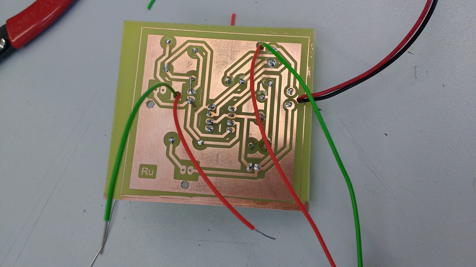
Finished.jpg
Initially, on testing, the single red LED would light up brightly then the other red and the green would come on very dimly together but then just stay on. The timer and layout of the circuit were supposed to cause a repeating flash of one red then red + green. Jamie and I checked through the circuit and I compared it to what Circuit Wizard had produced for me but there didn't seem to be an error. I disconnected the red paired LED and the flash started to work, so I soldered the red back on again and it all worked as it should. So I still don't know what the problem really was, but now it's all working.

Checking why it doesnt work.jpg
No comments:
Post a Comment
Note: only a member of this blog may post a comment.